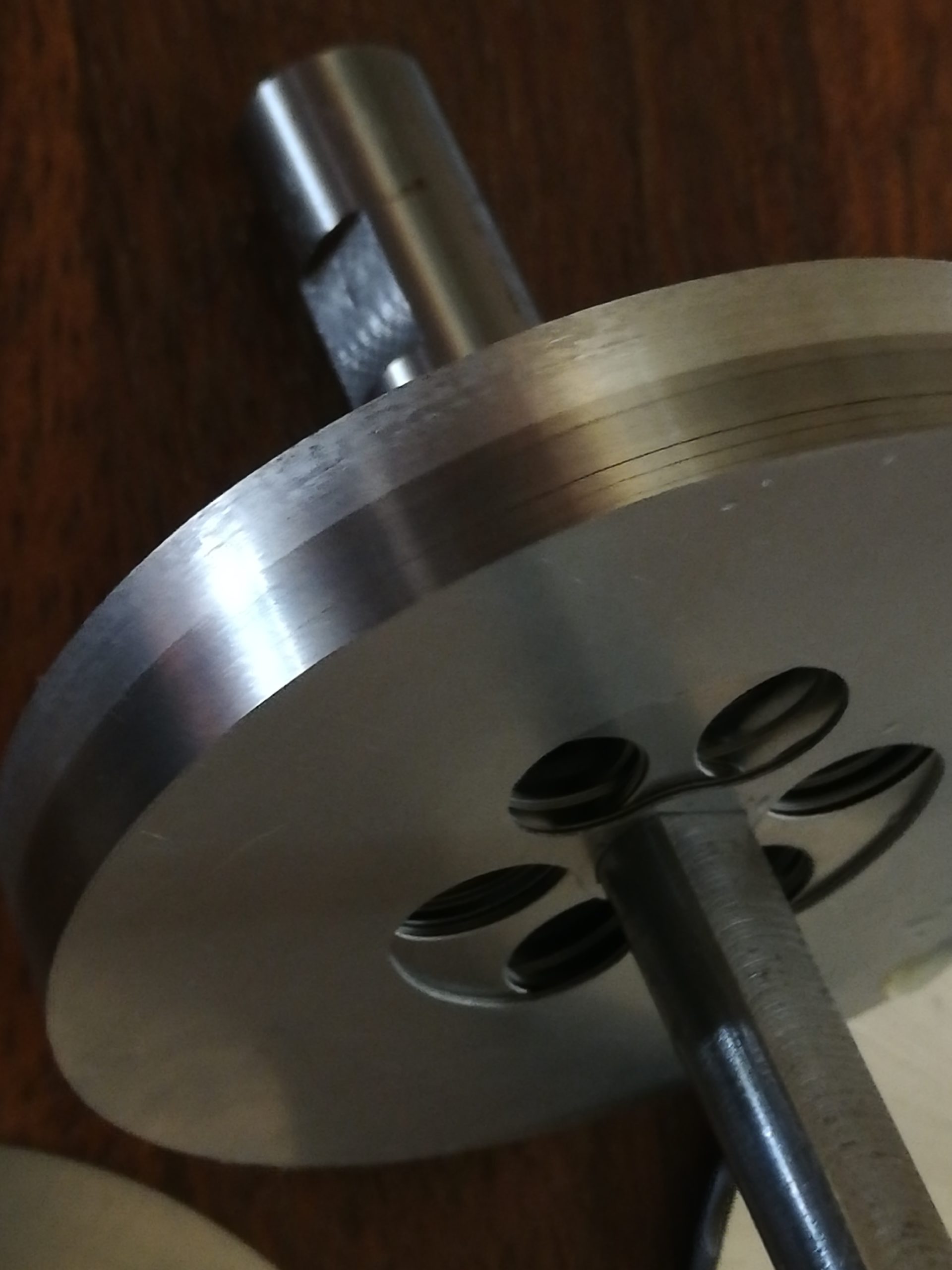
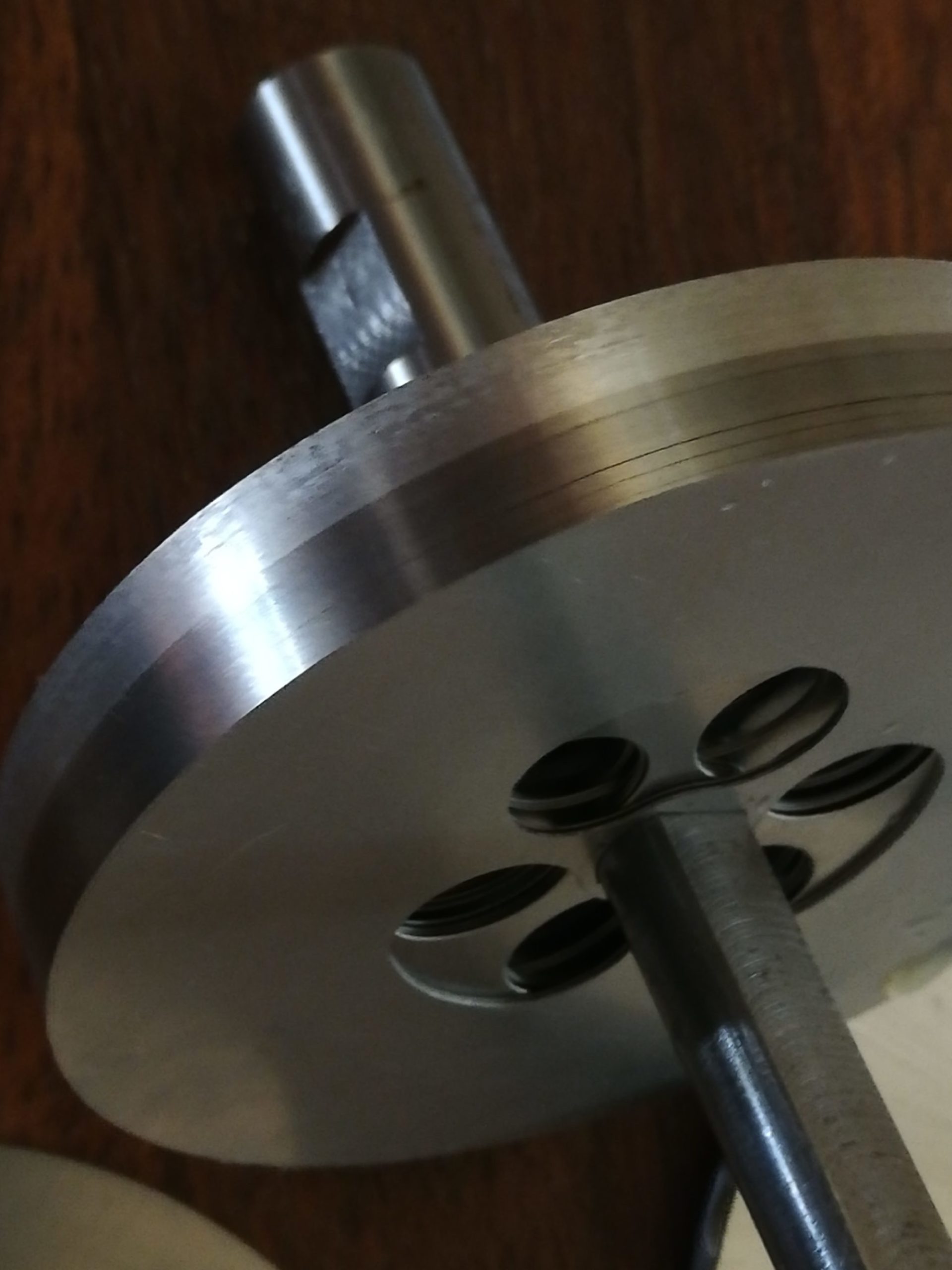
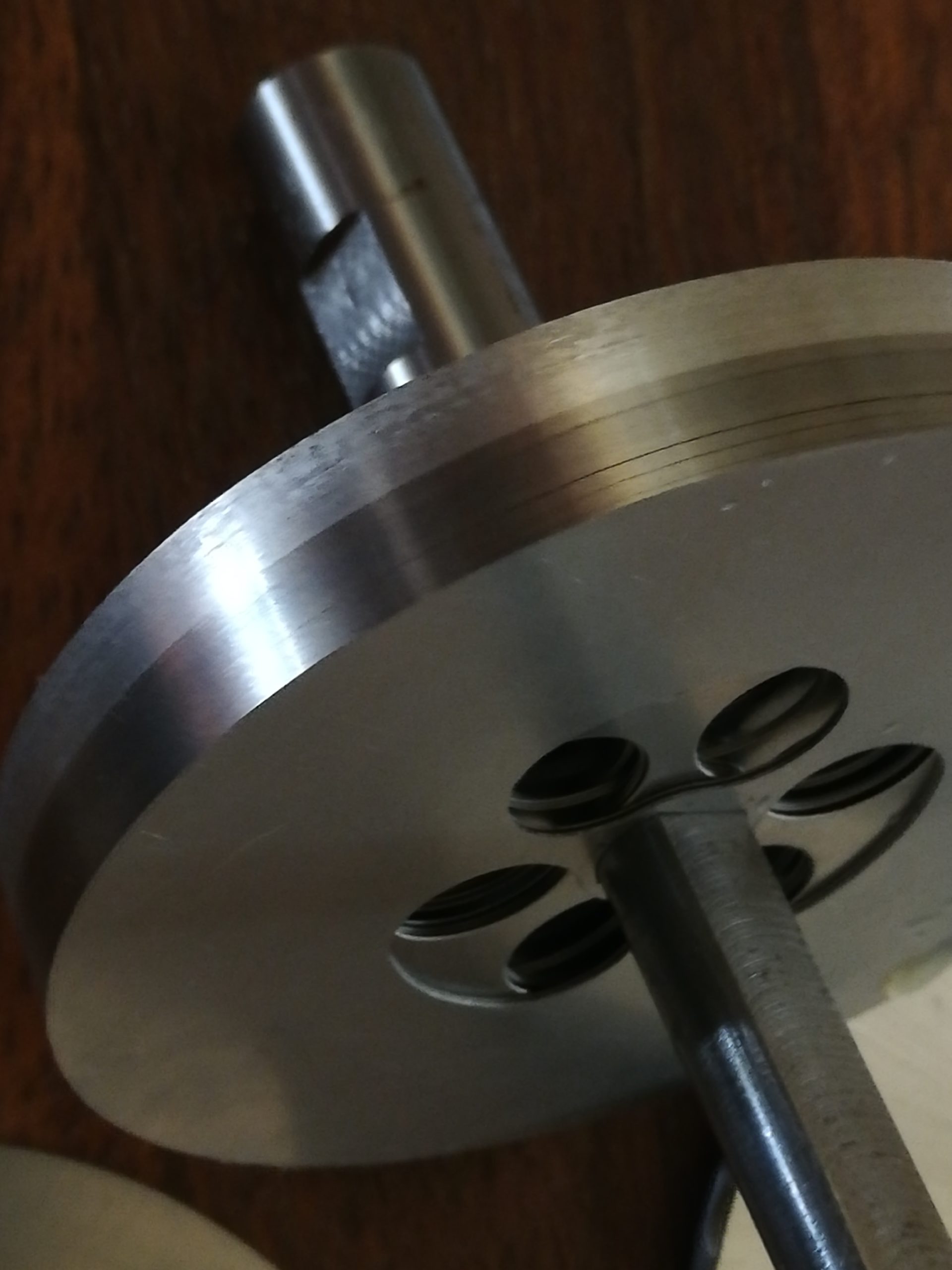
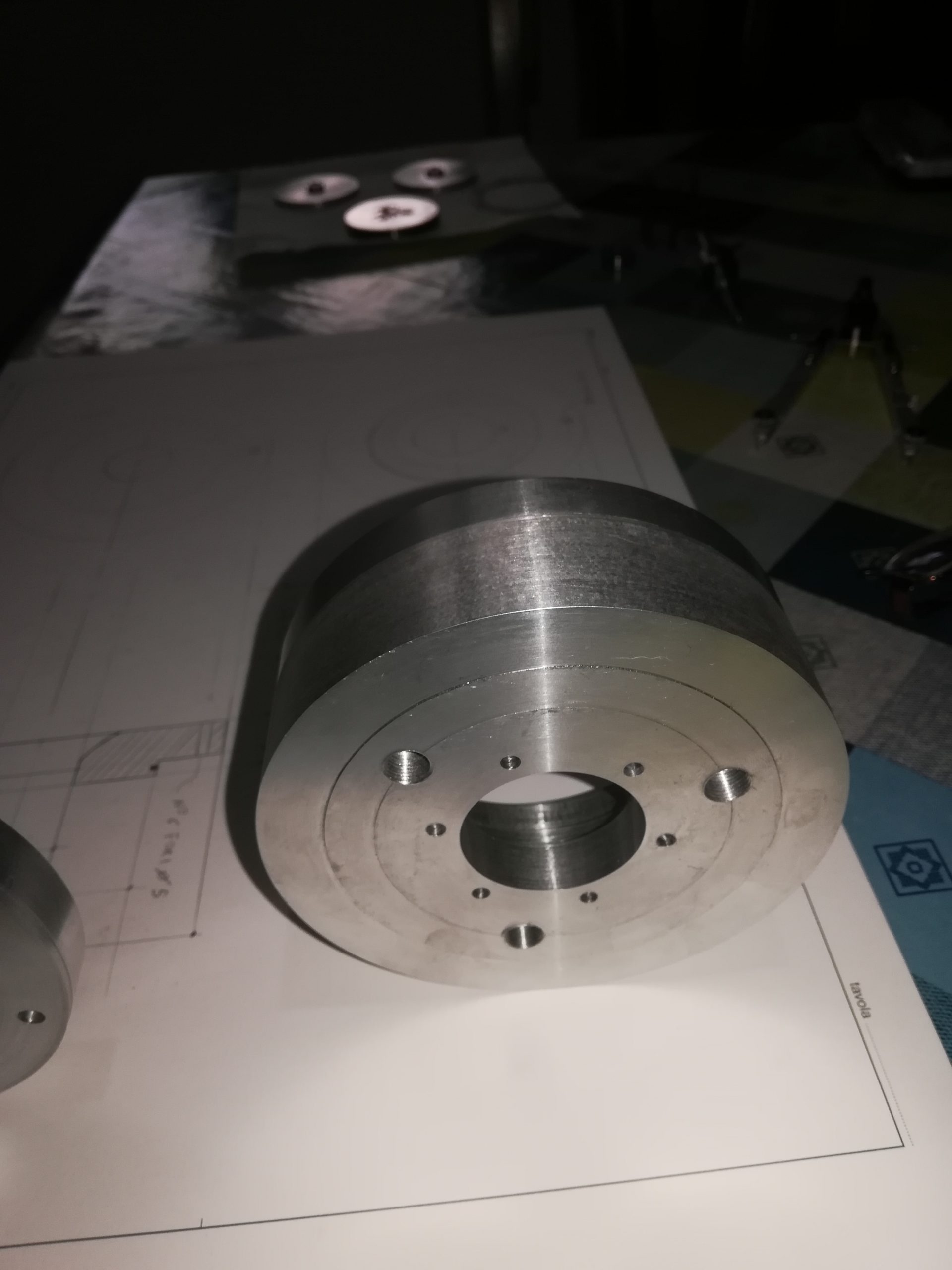
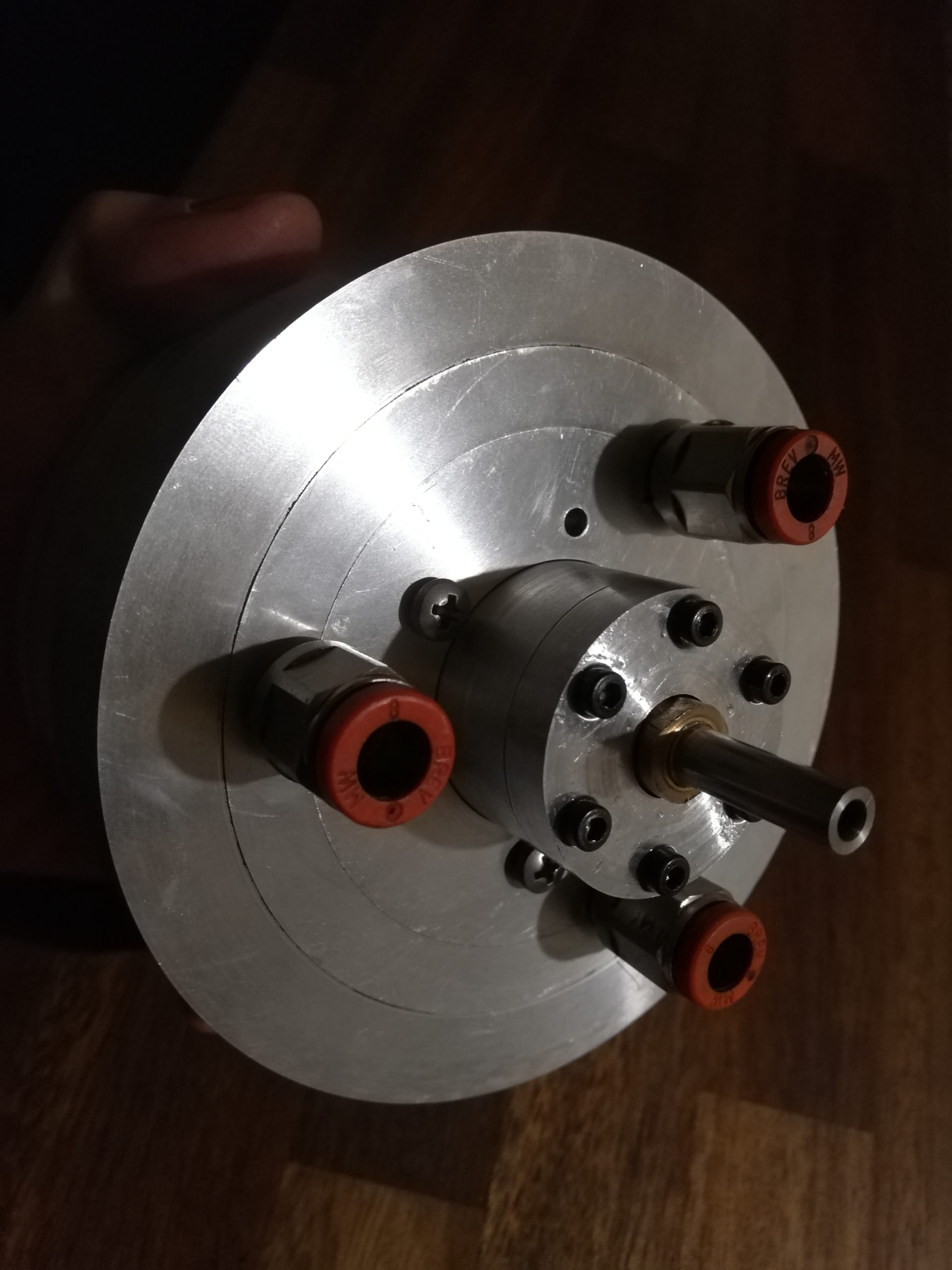
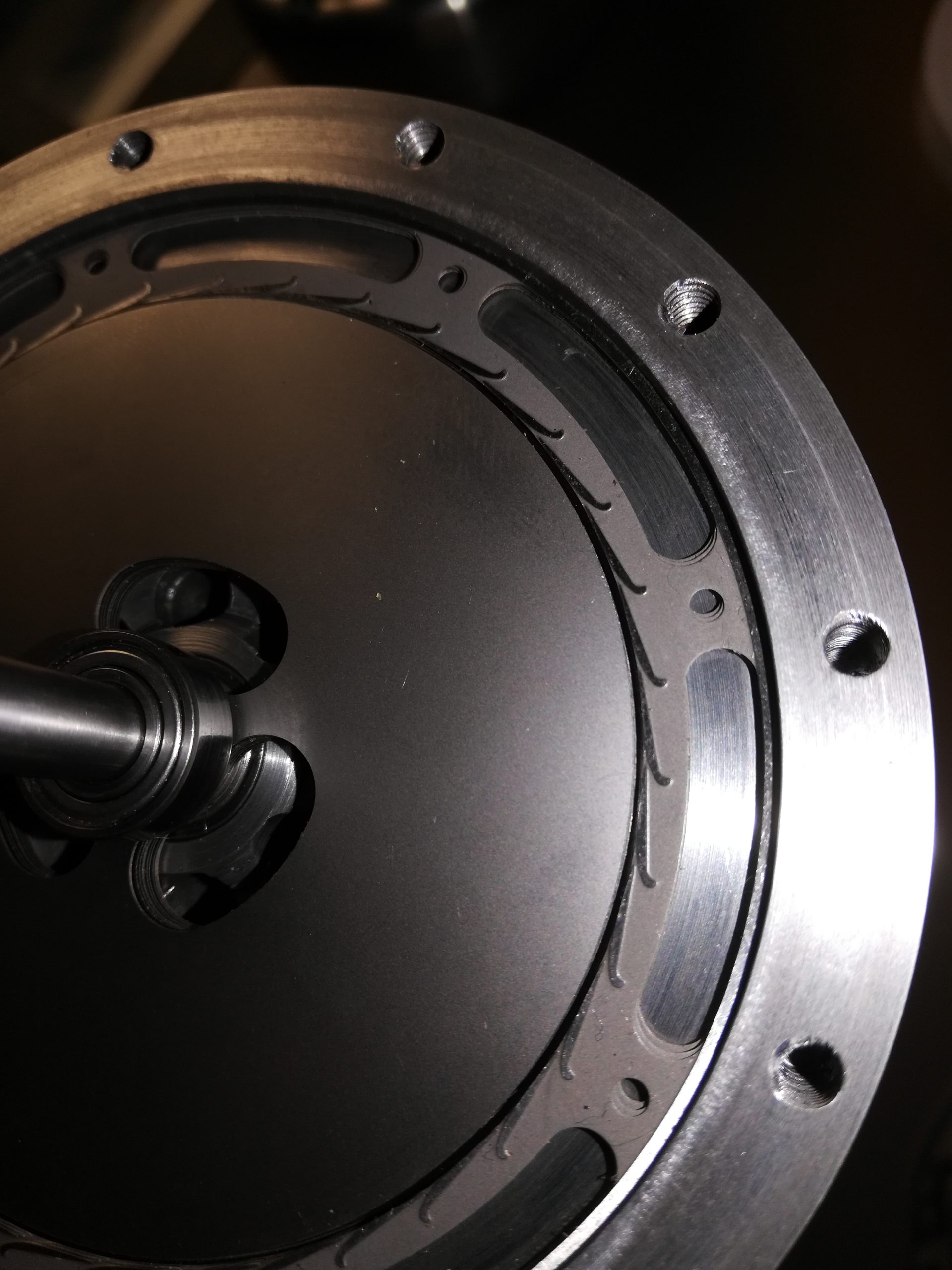
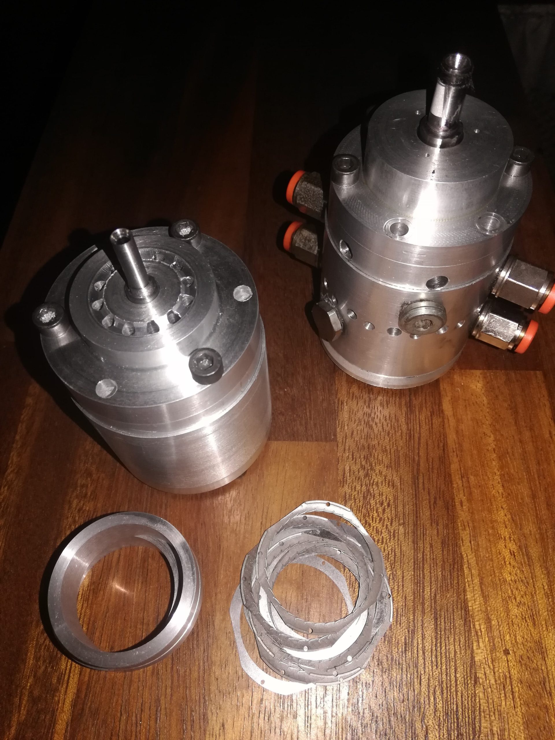
Main applications:
microturbines for cogeneration operating with pressurized fluid air – hot air – steam – or mixed gas / liquid fluid high speed pneumatic motors / spindles for finishing, grinding, micro drilling, or microturbines for medical use.
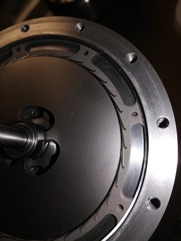
Main advantages at a glance:
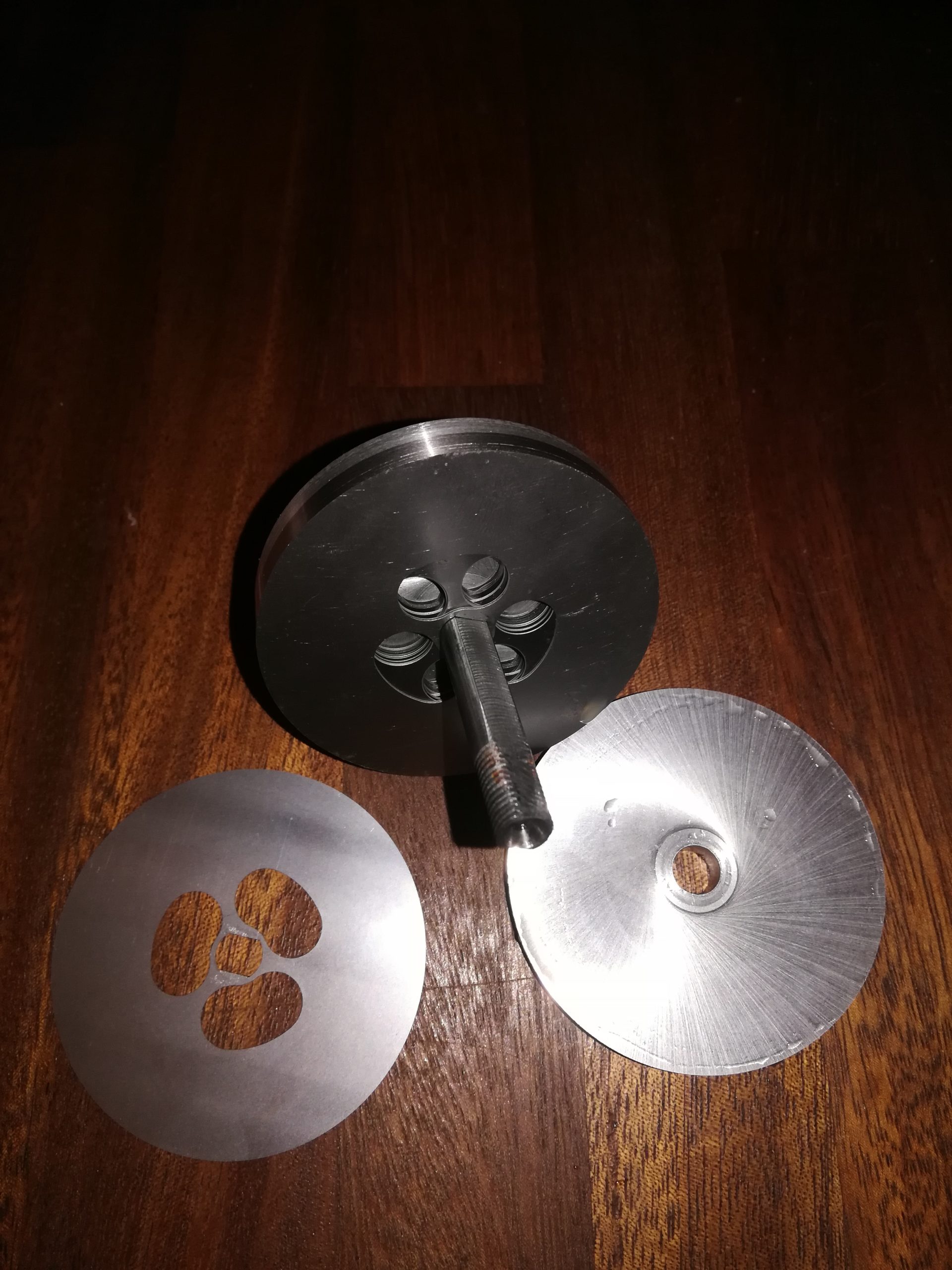
- Very low machine cost (stator and rotor made with chemical etching)
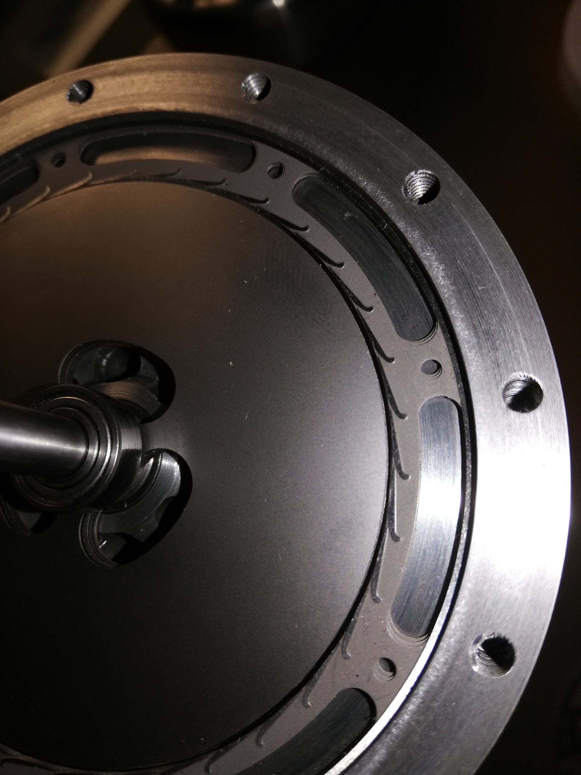
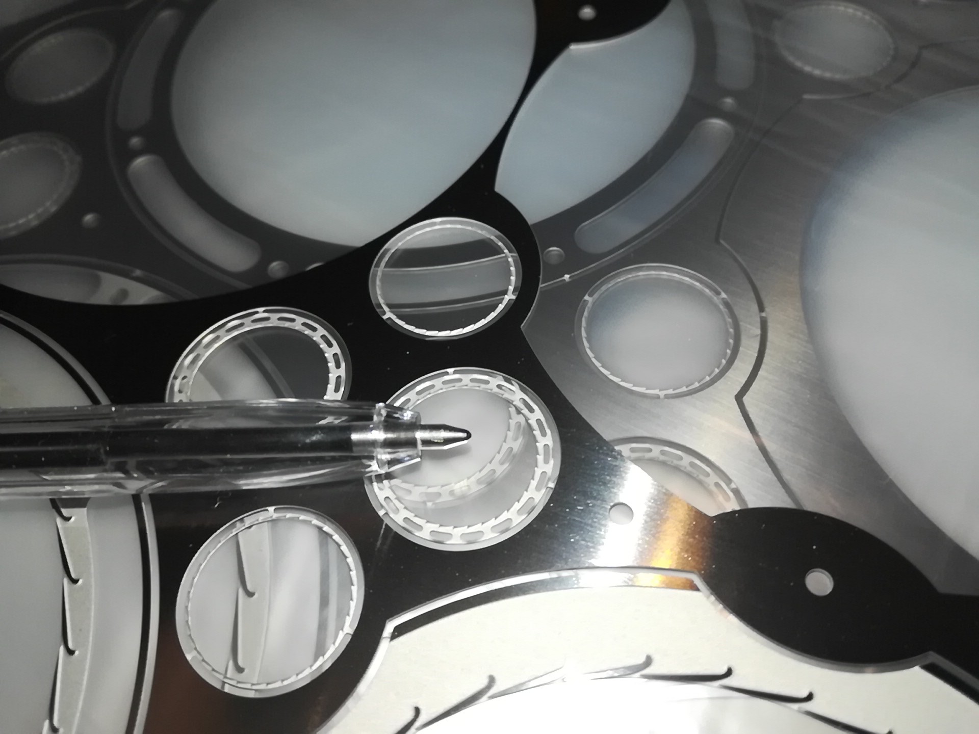
The micro nozzles stator made with photoengraving and shearing process guarantees high precision
(photographic quality) in the realization of the shape and orientation of the flow passages regardless of the
micrometric dimensions and density. Process, working times and relative costs are very low and not
related to employed material (brass, bronze, copper, aluminum, AISI 304 3160 321 301 stainless steel,
inconel, surgical steels, etc. etc.)
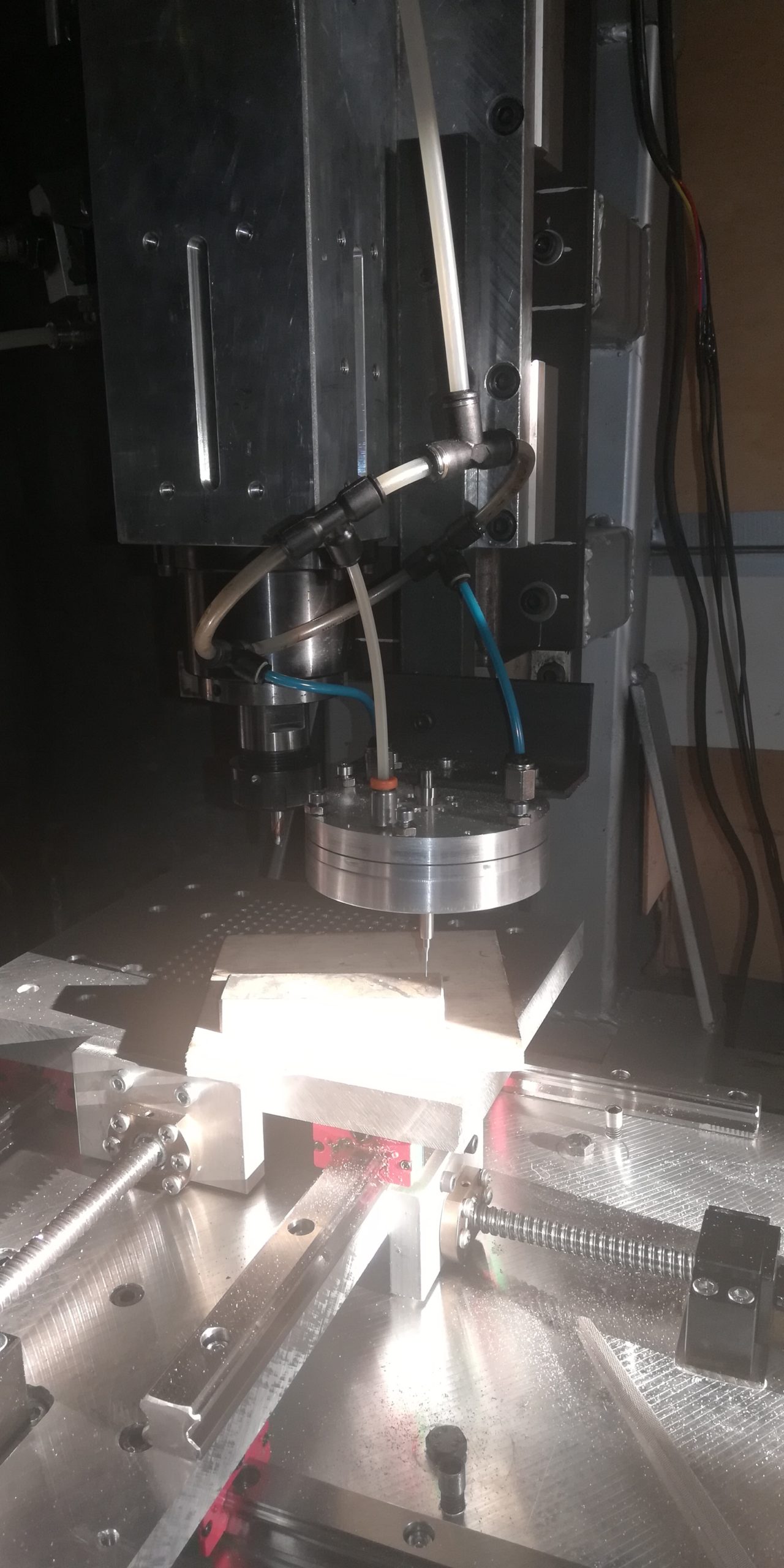
No tools or cnc machines are required to make the rotor and stator parts. resulting in a significant
reduction in costs.
- Fluid of any nature (insensitive to the impurity of the feed air and maximum diameter of the solid
particles driven in the order of the steps of the stator nozzles) - Absence of vibrations (there is no alternation of blade / fluid passage)
- Very low rotor wear for the small gap between the fluid-rotor speeds.
- The torque reaches maximum at the start, increasing as speed decreases
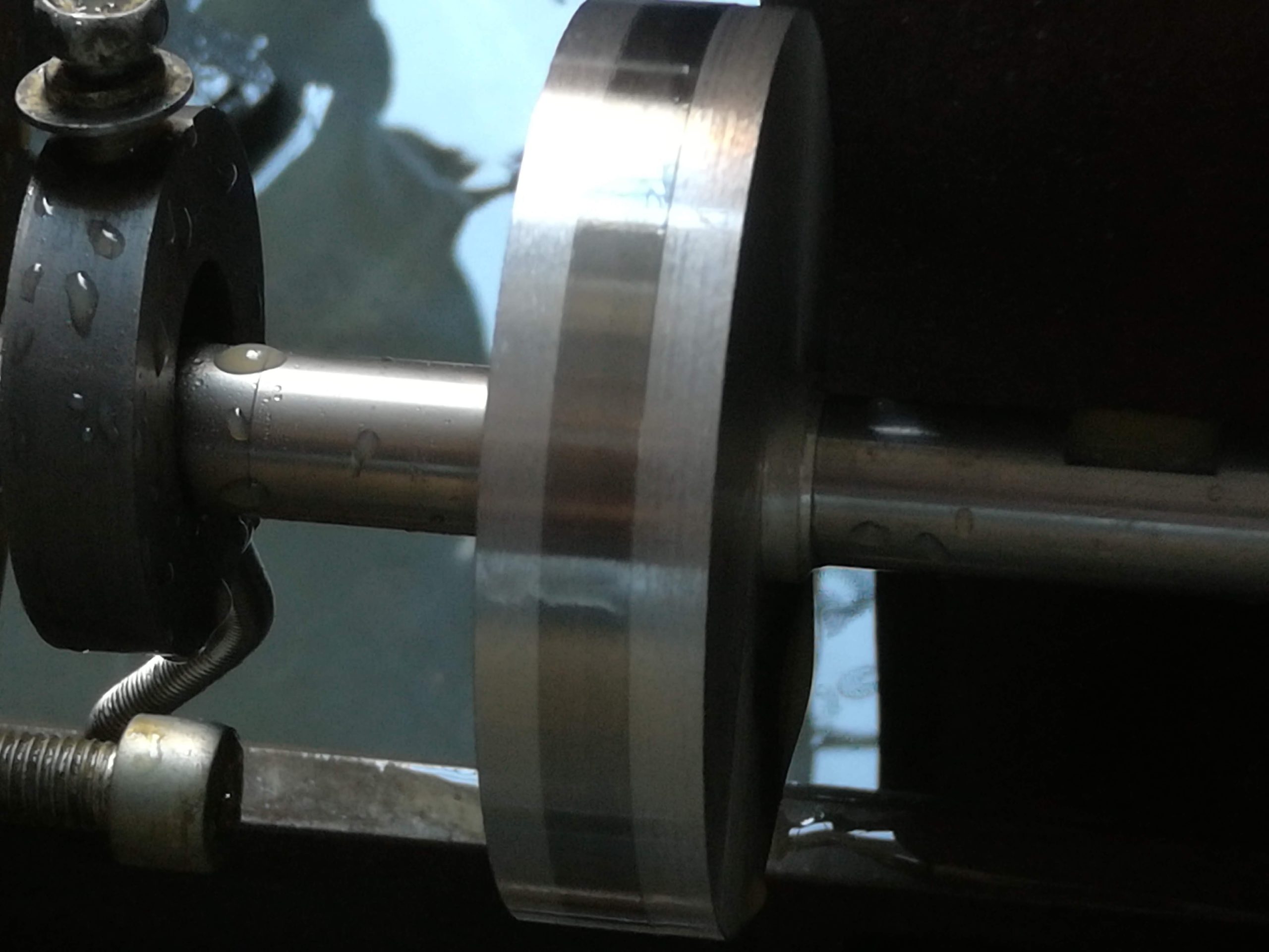
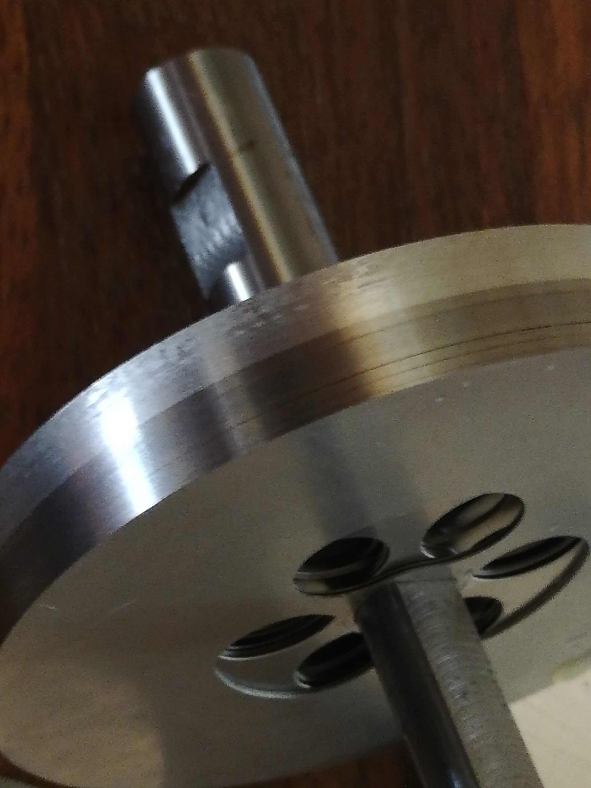
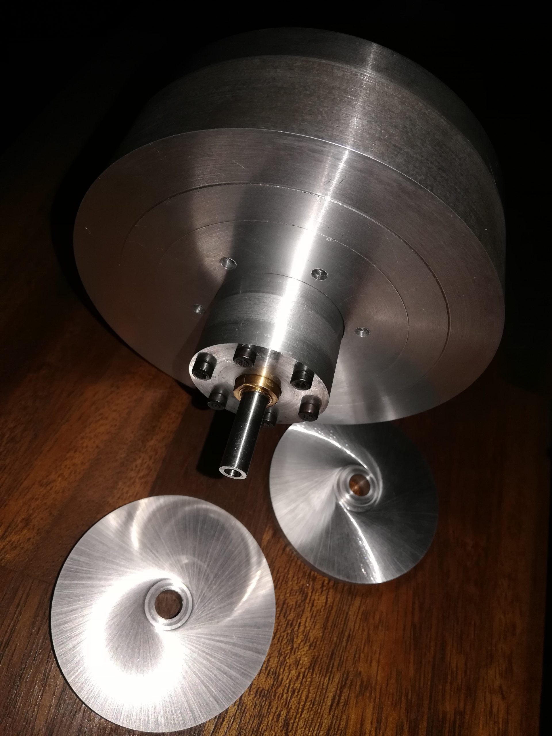
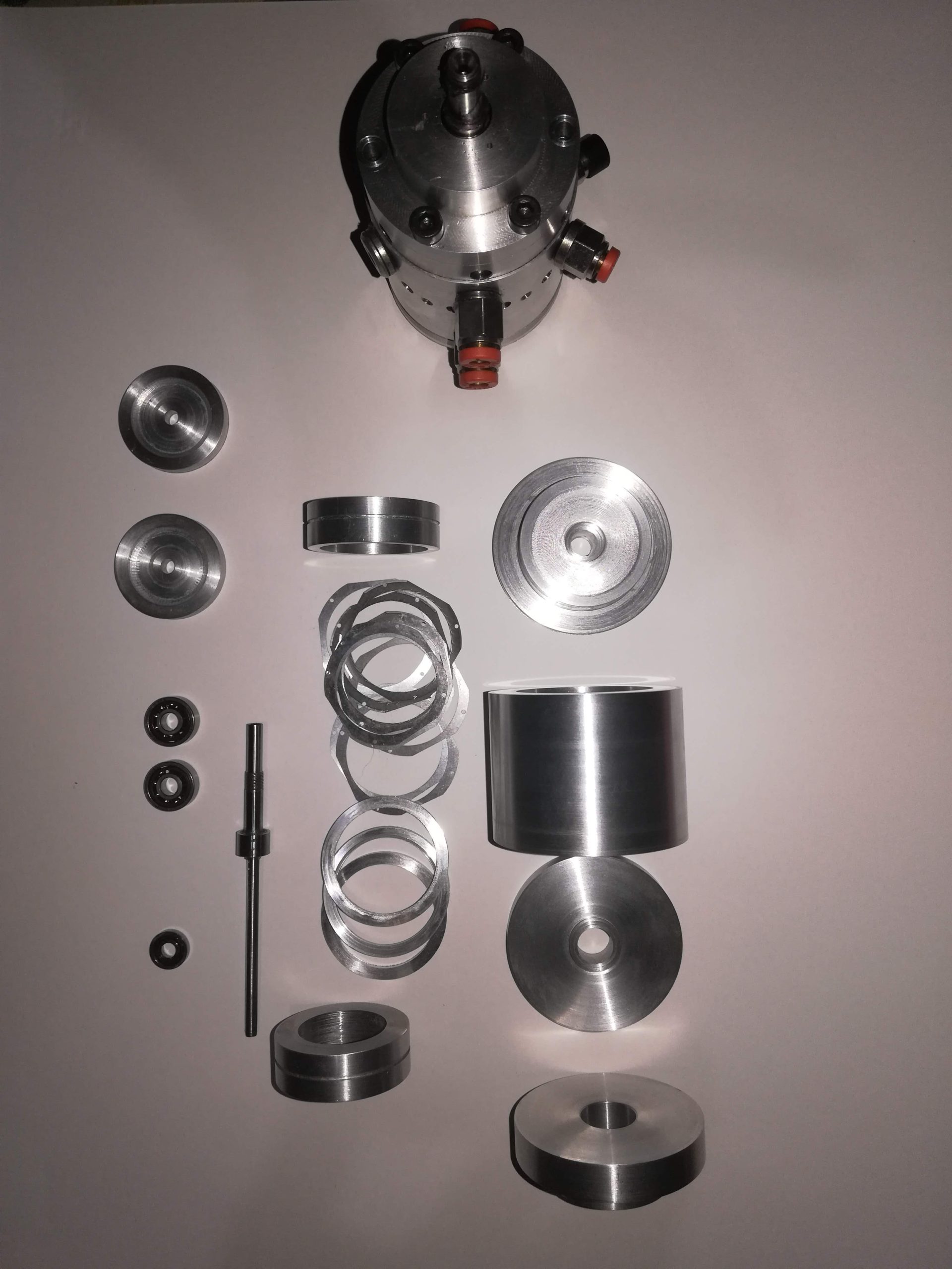
- Modular machine: the required power (torque) can be obtained by suitably varying the number of rotor
discs in relation to the flow rates and pressures of the available fluid. - Insensitivity to changes in feed pressure: efficiency and maximum speed can already be obtained with a
pressure at the stator nozzle inlet of 1 relative bar (2 absolute bar)
This kind of invention, referring to the sector of small or very small dynamic fluid machines (driving or
operating), brings an improvement in performance and production costs by means of a new design and
construction approach.
It consists in particular of two steps:
- change of design philosophy: we pass from a small number of large cross-section passages
within which thermodynamic transformations take place, to a machine made up of hundreds if not
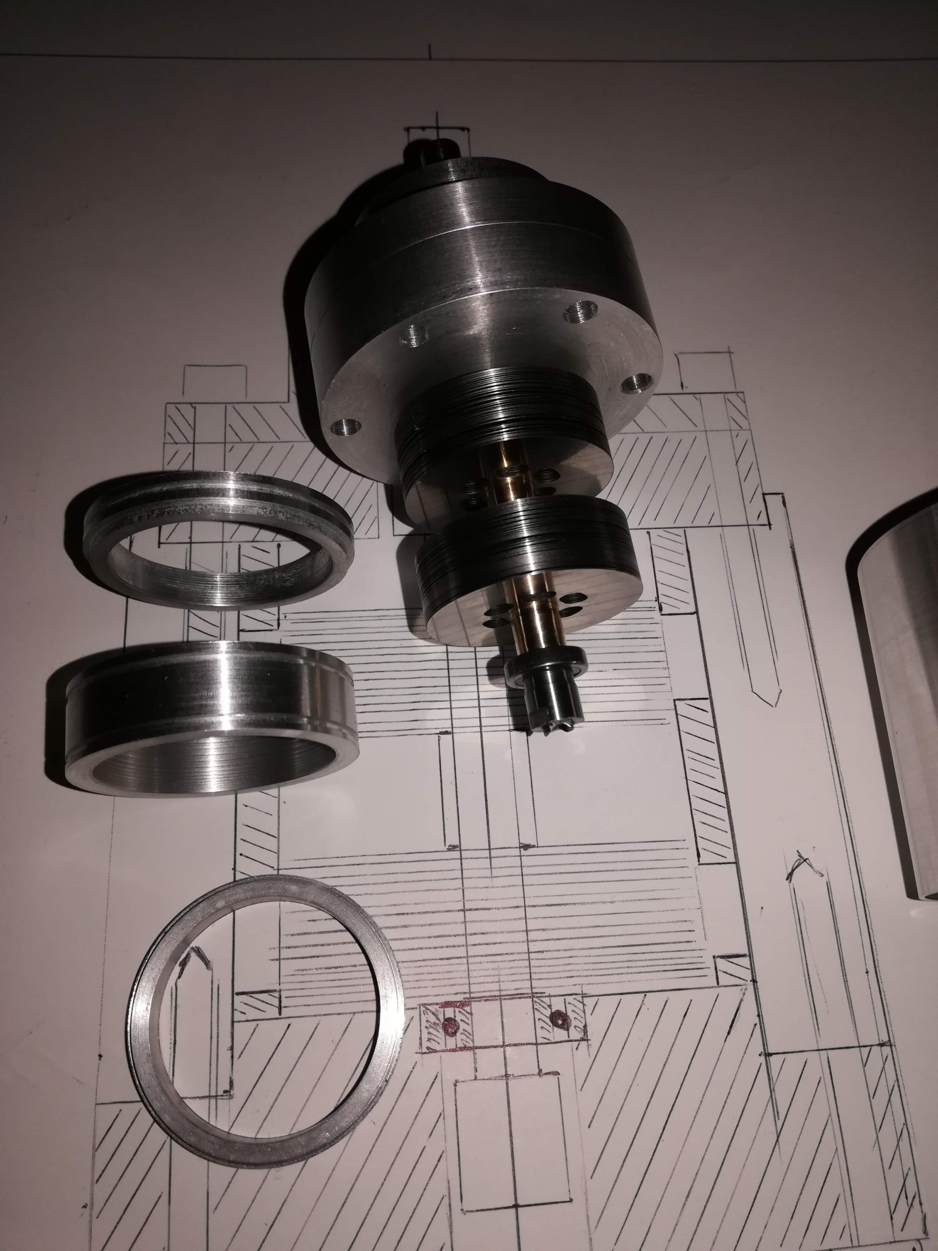
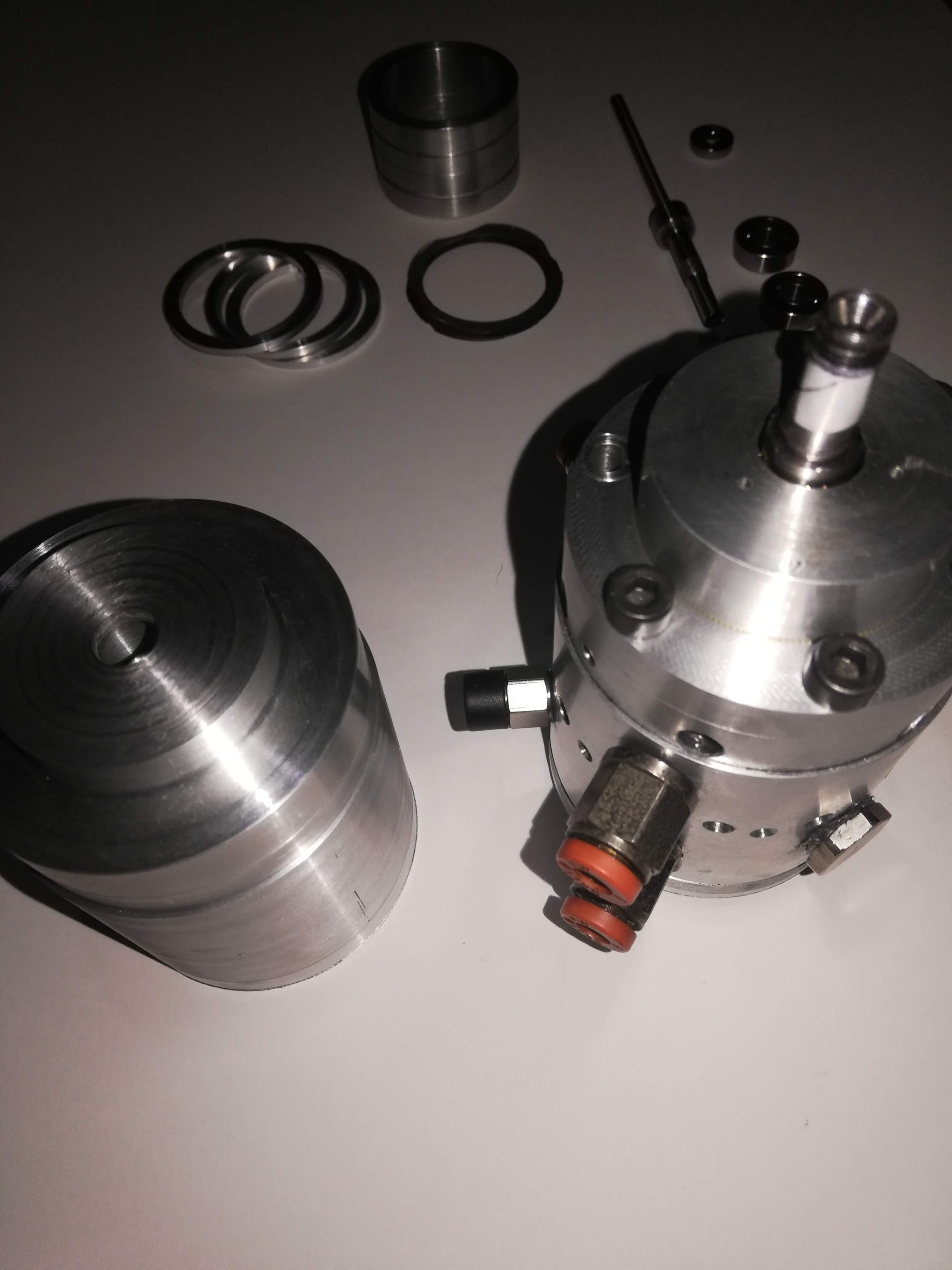
thousands of passages with an almost microscopic section (“porous” machine) . - Change of the way in which the machine is built: we pass from a concept of machining from solid
to a quasi-additive one as a large number of sheets of different shapes are stacked to obtain the three-
dimensional shape of the finished machine (lamellar machine) .
State of the art
At the state of the art, solutions are known to obtain the thermomechanical transformations required as in
dynamic fluid machines (both driving and operating) there is the transformation of the energy contained
in a fluid (enthalpy) into mechanical energy and vice versa. To obtain these transformations, there must
be interaction between the fluid and a moving mechanical organ. Of course, these transformations occur
only if the fluid is suitably guided through nozzles (or vanes) in order to transform its enthalpy into
kinetic energy and therefore into forces and vice versa. The position of the nozzles (or vanes) can be
indifferently on the stator or on the rotor or on both depending on the type (degree of reaction) of the
machine.
In most small-sized machines, the number of nozzles (or vanes) usually does not exceed twenty, this
involves along the development of the rotor / stator boundary a discretization of this boundary in areas
where there is flow and areas where there is no flow. there is as a wall: this alternation causes vortices and
strong friction on the walls since the radial component of the velocity is not zero and the gradient of the
velocity itself can reach very high values, also in this case with large losses in efficiency. Due to these
limitations, in fact, small machines are often of the reaction type (the enthalpy transformation occurs
inside the rotor) precisely to avoid the formation of many vortices at the entrance to the rotor, with a
significant loss of power and yield.
Further problem with these machines is their lack of flexibility in changing the required specifications:
once a machine has been built, this machine is a single piece that cannot be modified, if there is a change
in the specifications that leads to the outside of the operating range, it is necessary to completely replace
the machine. Furthermore, it is difficult to find on the market the machine that perfectly matches the
design requirements except in rare cases.
Aims of the invention
To solve the problems listed in the previous paragraph, it has assumed a kind of machine in which the
flux is distributed practically without continuity solutions along the entire stator-rotor boundary
circumference.
The main conception of this type of machine is to distribute the inputs / receipts of the motive fluid along
the entire boundary circumference, in order to minimize the sliding of it on the walls and therefore try to
limit the friction losses on parts that are not generating work, limiting as much as possible the velocity
components not tangent to the surfaces.
Virtually almost the entire stator-rotor boundary is the seat for the passage of the motor fluid. Of course it
is not possible to obtain the limit condition of fluid passage without solution of continuity, also because it
is necessary to direct the fluid. Therefore we try to make the passages processing the fluid as small as
possible to minimize the pressure and velocity fluctuations along the stator-rotor boundary circumference
and to limit as much as possible the length of the turbulent trails left by the walls between the fluid
passages.
Furthermore, the flow rate processed by the machine is defined by the rotor and the presence of a large
number of stator nozzles of too large dimensions easily leads to choking of the same, causing a decrease
in the available pressure jump on the nozzles and a drop in the efficiency of the same.
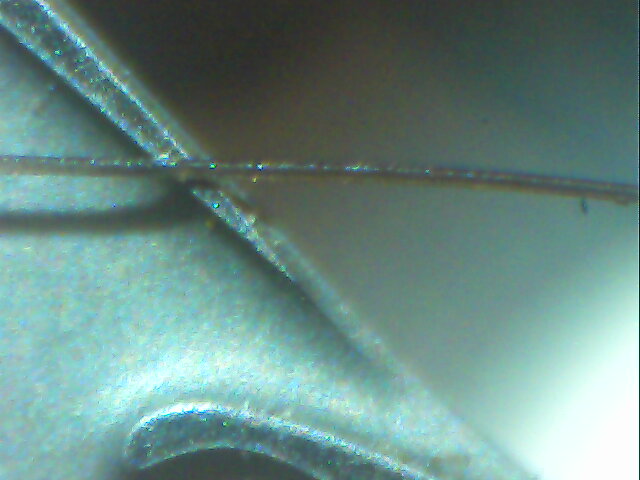
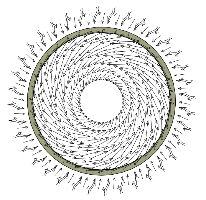
From the union of these two ideas, we came to think of a “porous” stator: a stator in which the nozzles are
very large in number (even several hundred) and very small in size
- However, the need to minimize the size of the vanes (or nozzles) leads to several problems:
- First of all, the need to keep the passage section between the blades tending as much as possible to the
circular shape, to limit the section soaked by the fluid and maintain the friction to a minimum. - Technological limits of conventional machining, as it is not possible to think of being able to make too
small passages with mechanical machining, even without taking into account the obvious cost limitations. - Machine construction time limitations: a stator of this type must also contain several hundred nozzles
and the machining time from solid for such a significant number of passages is not acceptable. Even
thinking of building the stator with additive technologies (3d printing), current technologies do not allow
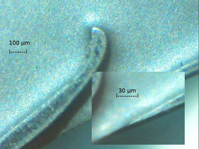
the construction of the stator with the necessary precision (the passages must have dimensions even less
than a tenth of a millimeter) and sufficient resistance (stresses, high temperatures fluid).
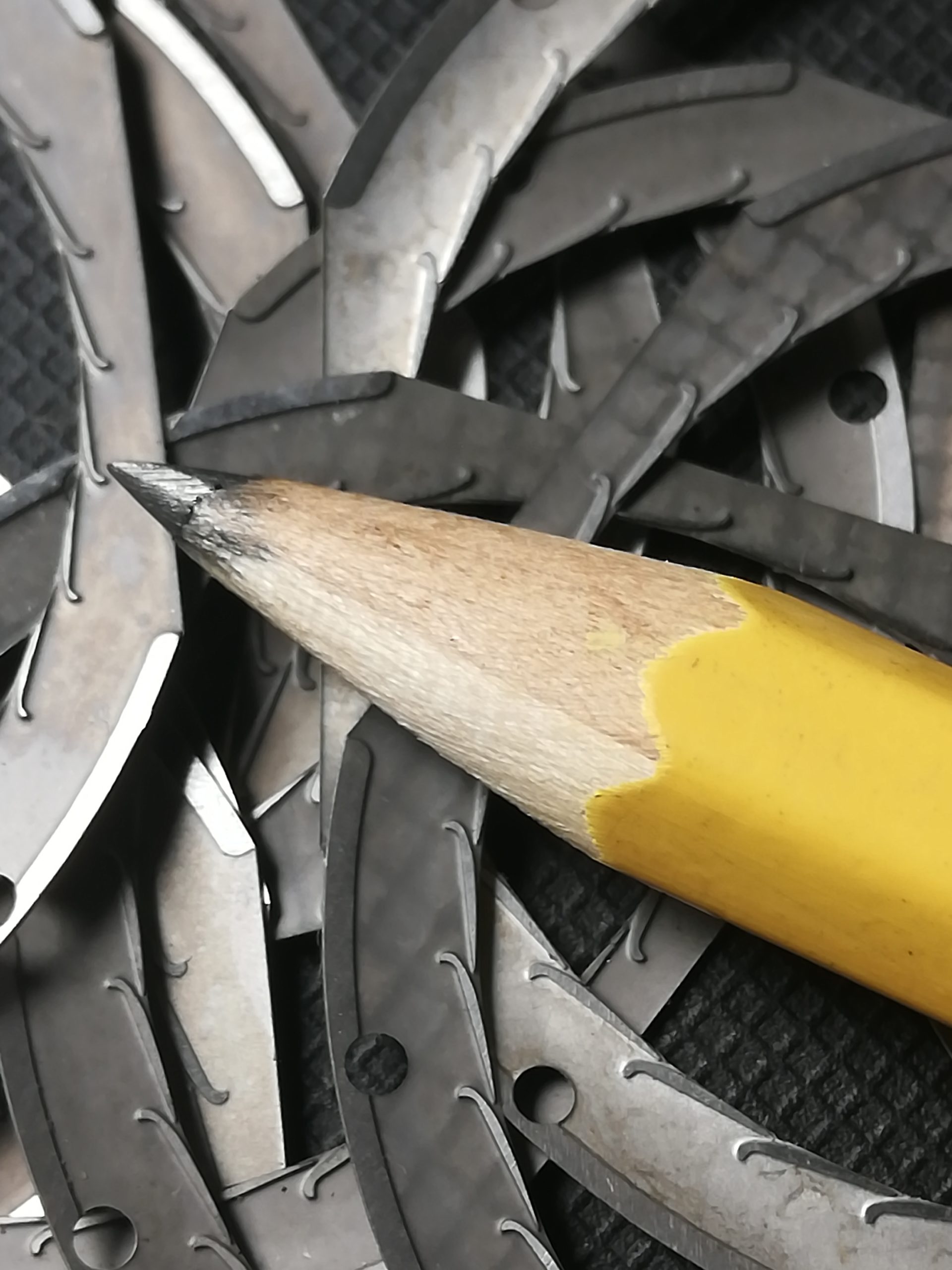
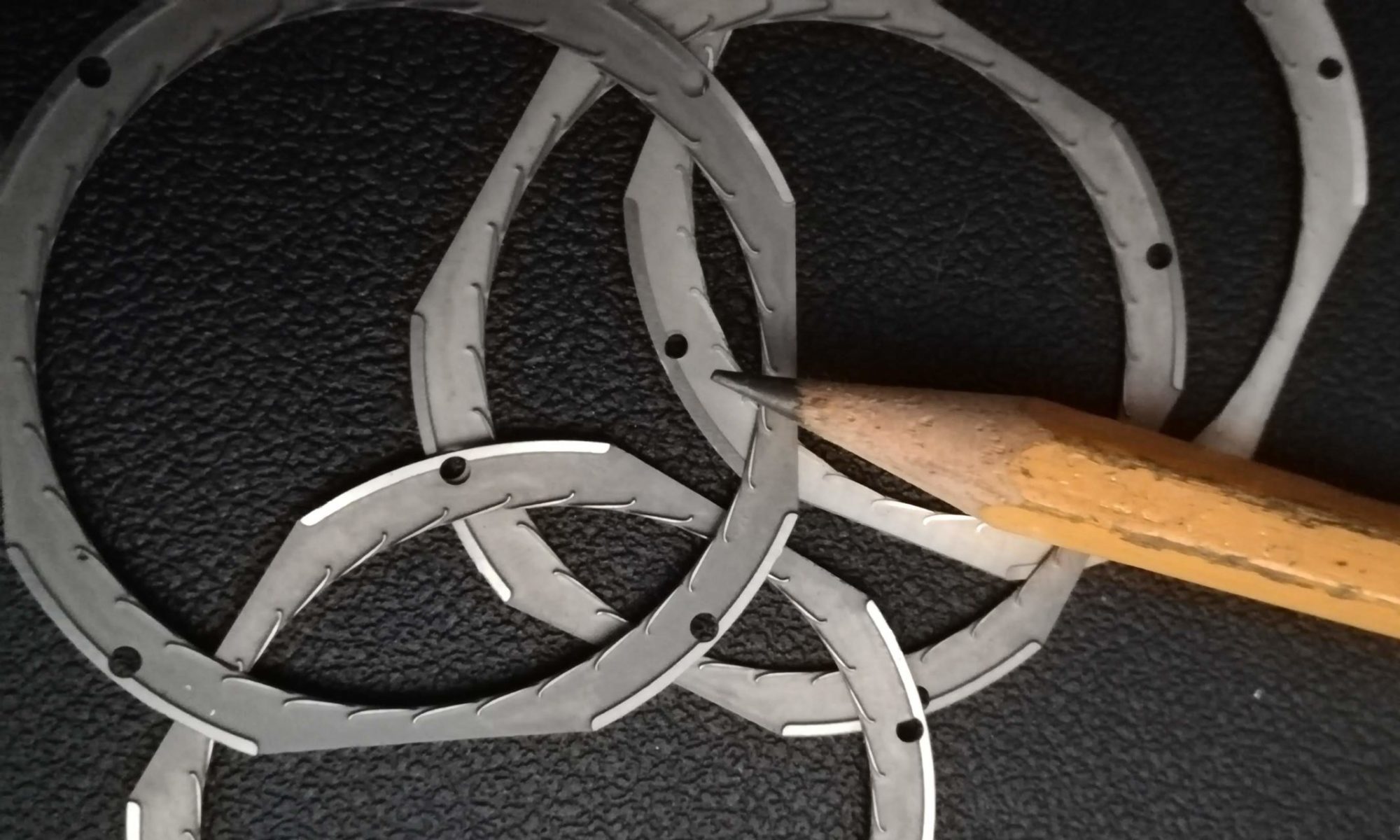
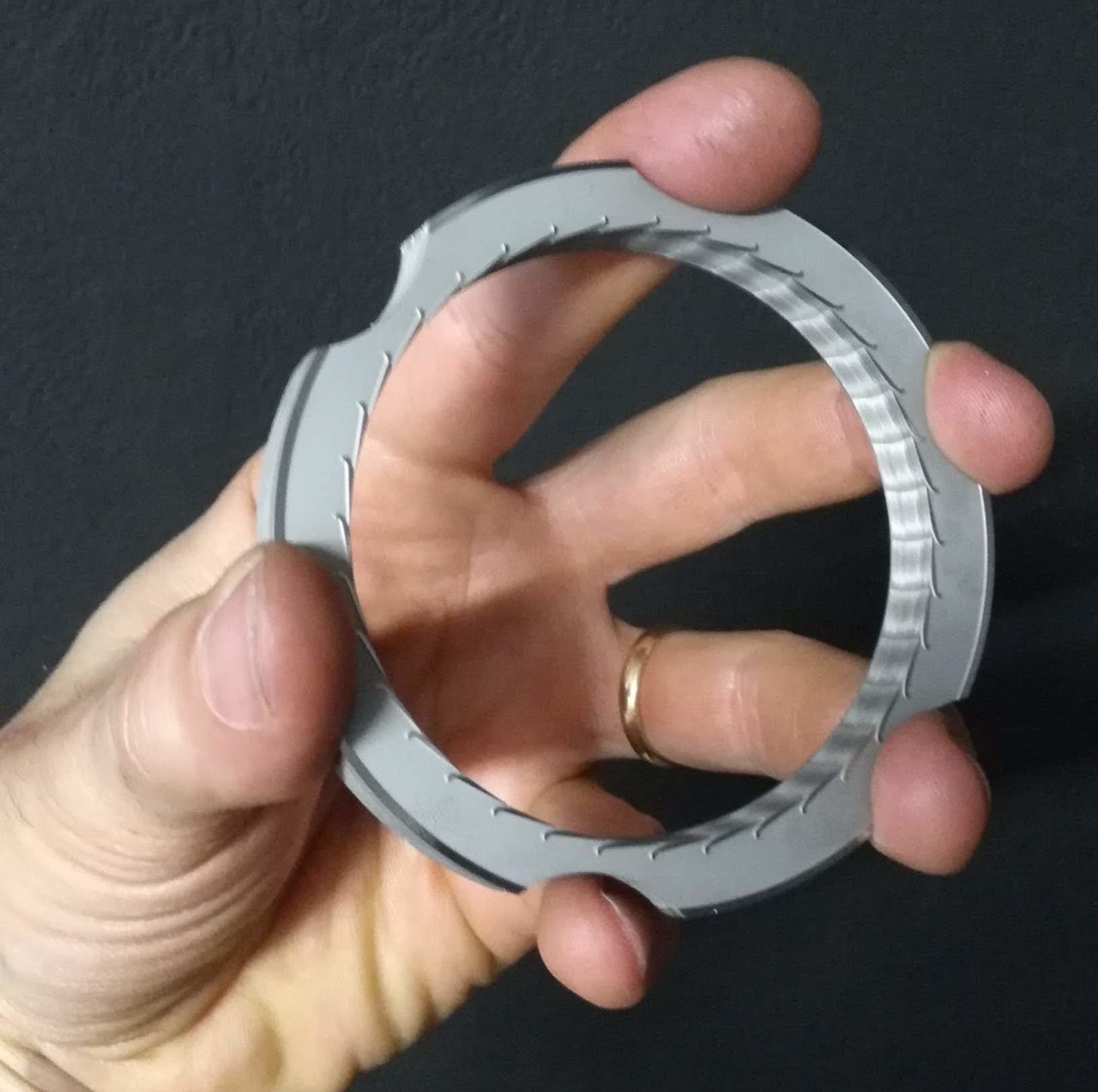
To overcome these problems, it was thought to build the stator with a fairly high number of layers.
With this system, with the machine already built, it is also possible to modify at will the number of foils,
their shape, the size of the passages without changing the carter of the machine and in a very fast and
inexpensive way, that is, a different machine is obtained in little time and with little expense, without
having big equipment.
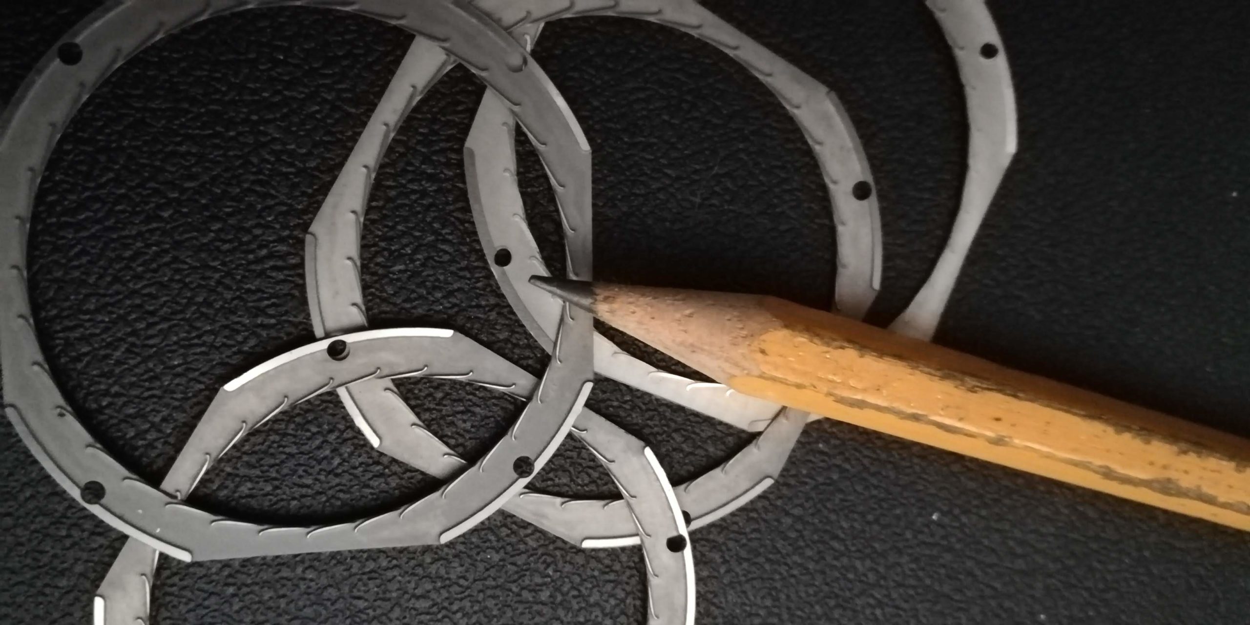
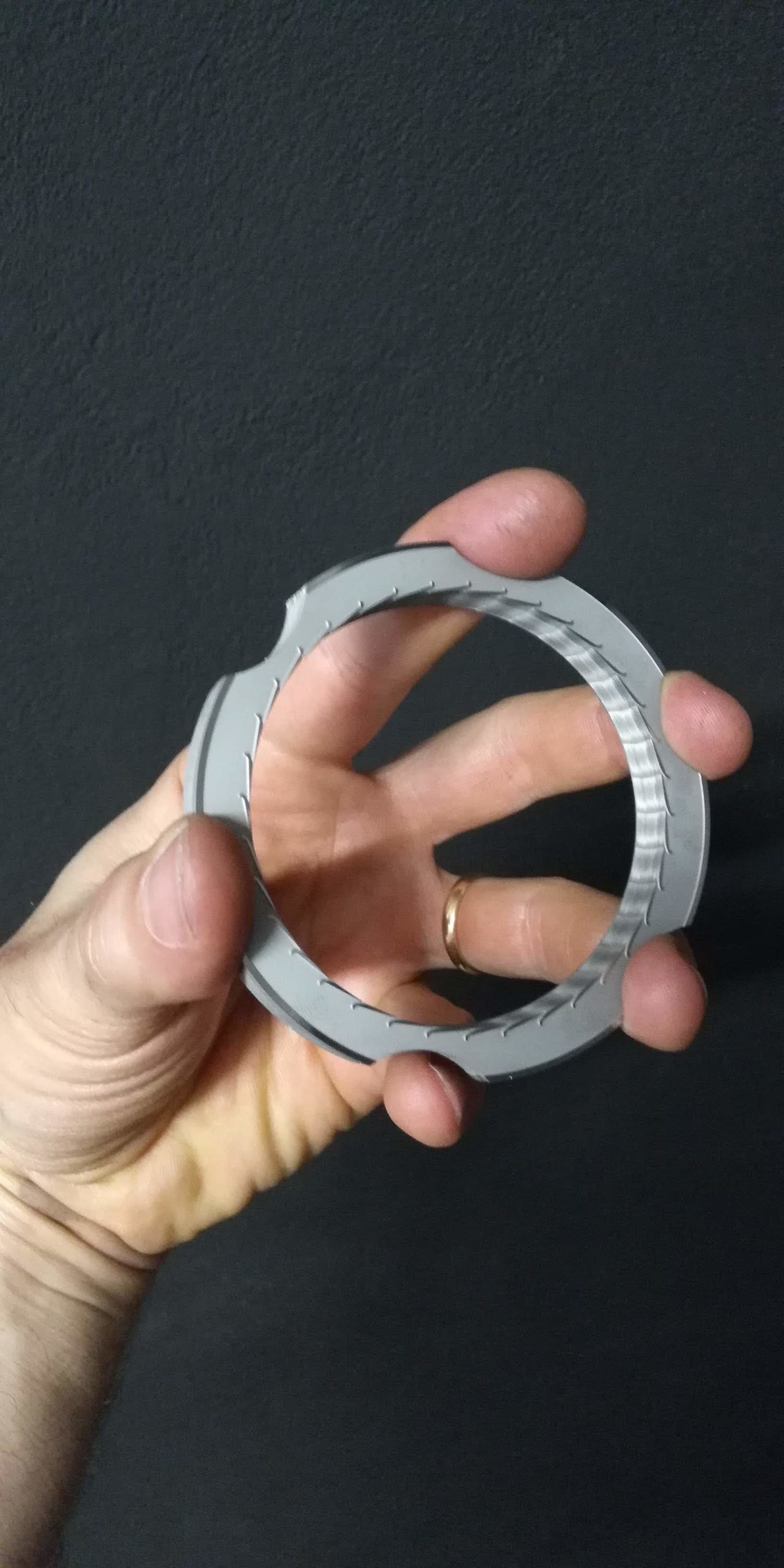
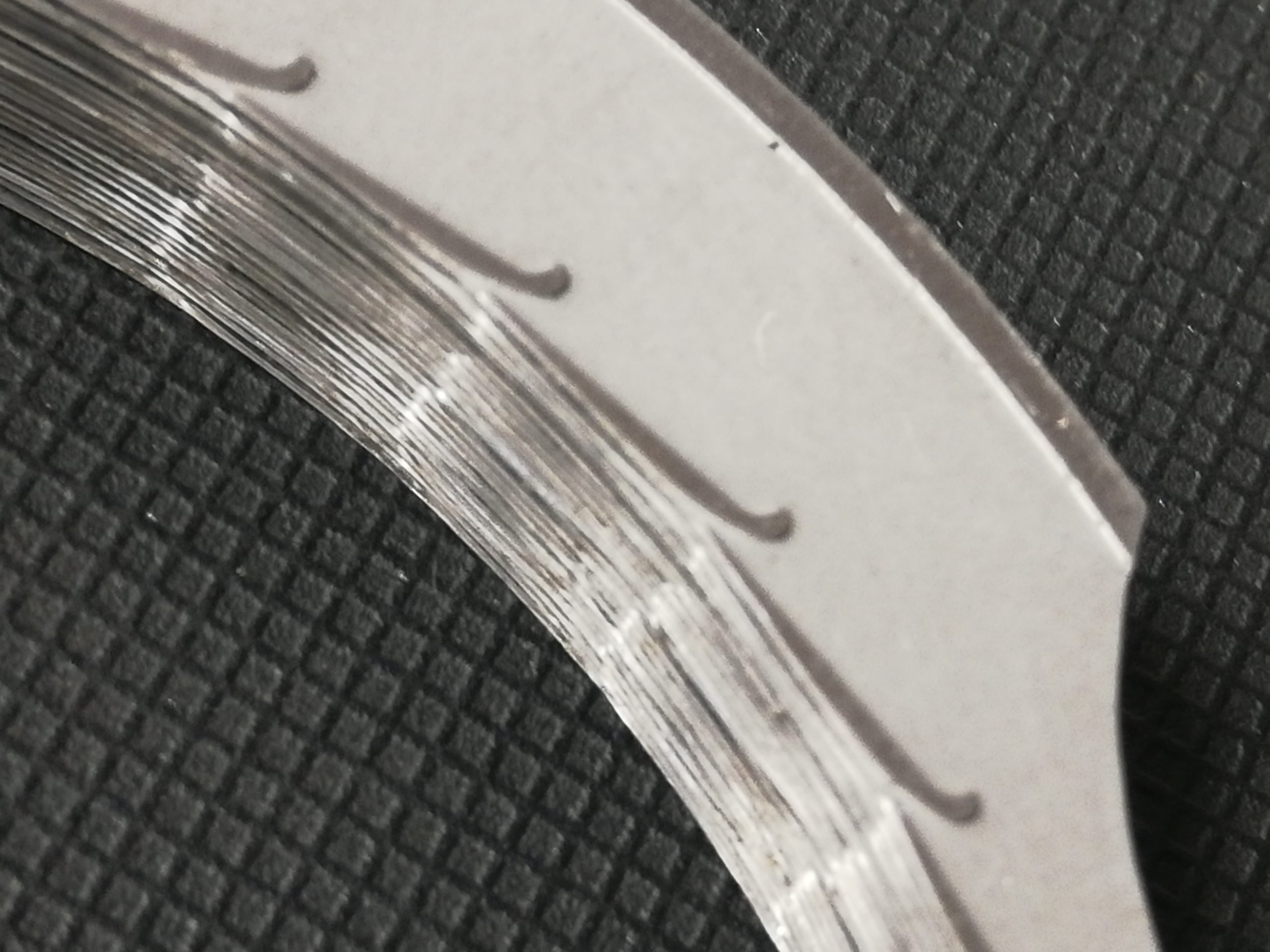
The shape of the nozzle (or vane) is engraved in each individual layer by chemical etching.
This procedure allows to obtain unthinkable precisions compared to other types of mechanical processing,
the material basically maintains all its mechanical characteristics, it is a very economical, fast and
inexpensive procedure, suitable for mass production.
Furthermore, in this process, by making the chemical attack take place only on one side of the sheet, it is
possible to directly obtain the array of nozzles (vanes) fixed to a half-thick sheet, which is a very sturdy
structure that can be easily packaged to obtain the stator (rotor) with the required characteristics of the
passage section.
Micro nozzles polar array
vortex generating stator elements:
protected against counterfeiting by applying for IT patent 102018000007430 and the international PCT application
